Manuali VOIspeed®
VoiceBlue Next 2N GSM Gateway Configuration
VoiceBlue Next is a gateway that allows you to interface the VOIspeed SIP switchboard with GSM networks. It is available in two versions, 2 and 4 SIM, with external GSM antenna for better reception. The VoiceBlue Next Gateway is powered by a PoE system or external power supply.
Preparing the gateway for first use is quite simple:
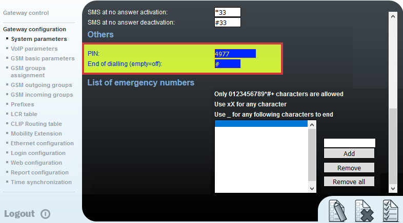
- Install the SIMs as shown, starting with slot 1. NOTE: Before inserting the SIMs, decide whether or not to use PIN protection. If so, set the same PIN on all SIMs.
- Connect the antenna, screwing it to the connector;
- Connect the LAN network cable (if PoE the device will turn on);
- Connect the power supply (only if the PoE power supply is not used);
Warnings: always disconnect the power supply if you want to extract the SIMs or disconnect the antenna. Also, never turn on the device if it does not have the antenna connected: you could burn the GSM module.
Network Parameters and Access [Ethernet Configuration Menu]
Connect the gateway to the LAN and to the power supply if provided
- The gateway has default IP 192.168.1.2.
- Using a browser connect to http://192.168.1.2. Obviously the PC used must be in the same subnet as the gateway (192.168.1.X).
- Enter username and password. The default username is “Admin” and the password “2n”.
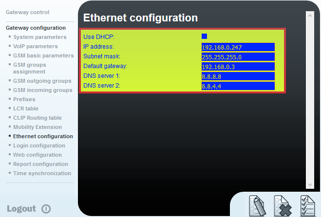
- Click on “Gateway configuration” and on the subsection “Ethernet configuration”.
- Set the desired network parameters.
- For Cloud / UCloud platforms, the dynamic IP can be kept (Use DHCP option)
- For the OnPremises platform, a static IP address must be set
- Click on “Save”
SIP Parameter Configuration [Voip Parameters Menu]
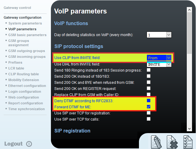
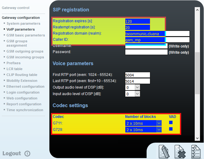
Variant for the ON PREMISES platform
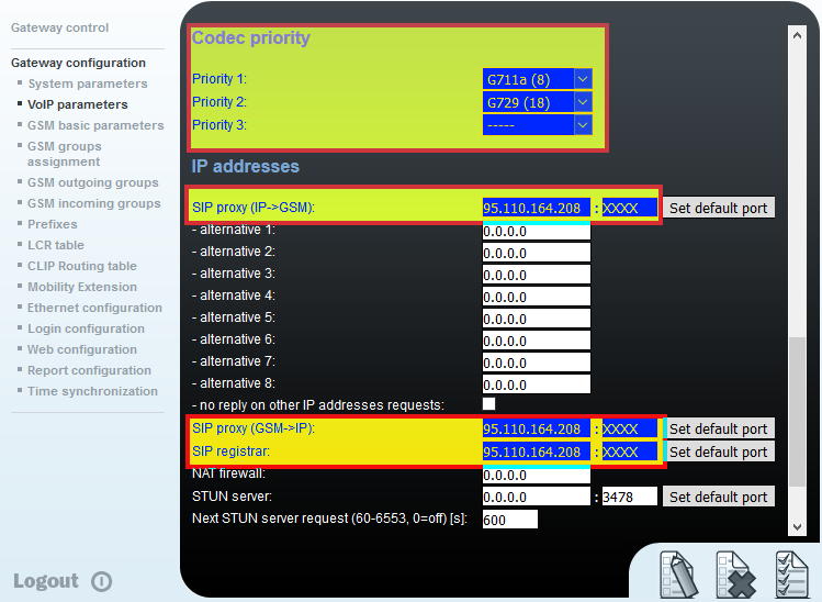
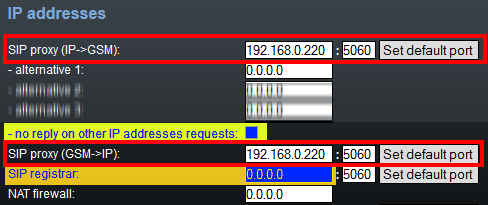
The platform with stand alone server does not require registration with the gateways, therefore the configurations change as follows: in the Voip parameters section, modify the following values
Security option
To prevent unwanted requests from reaching the gateway by exploiting some network flaw, you can activate the no reply on other IP addresses requests option. This setting, which allows you to accept requests for sending calls only from the IPs indicated in the SIP proxy, appreciably increases the security of the device. It is also advisable to change the default credentials for accessing the device via the web.
GSM Parameters Configuration [GSM Basic Parameters Menu]
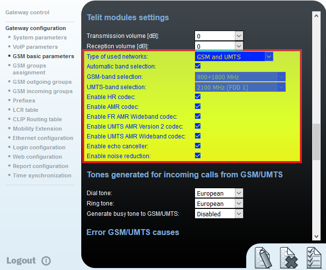
In the GSM Basic Parameters section, set the parameters as shown in the figure (for the sake of brevity they will not be rewritten)
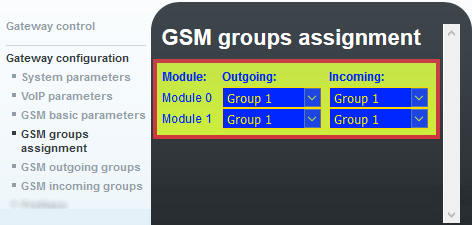
Group assignment [Menu GSM group assignment]
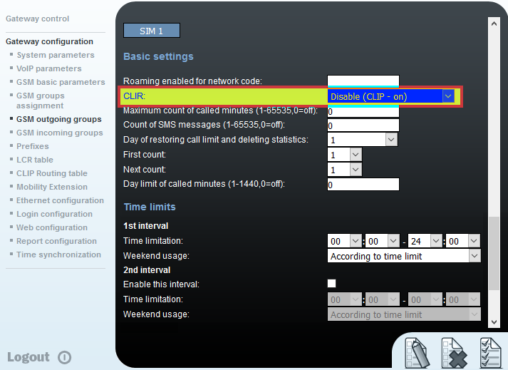
Outgoing Group Configuration [GSM outgoing group menu]
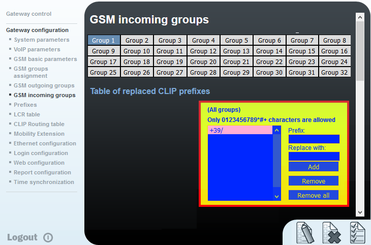
Incoming Group Configuration [GSM Incoming group menu]
This section manages the configurations for incoming calls to the gateway. In the table “Table of replaced CLIP prefixes” insert the string +39 in the Prefix field.
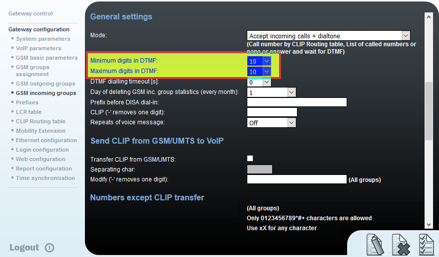
Set the Mode to Accept incoming calls + dialtone
Enter the value 10, in the Minimum / Maximum digits fields in DTMF (see figure below).
In some cases for short numbers it may be necessary to set the “minimum Digits” field to 9).
Set the parameter to 0: DTMF dialing timeout [s]
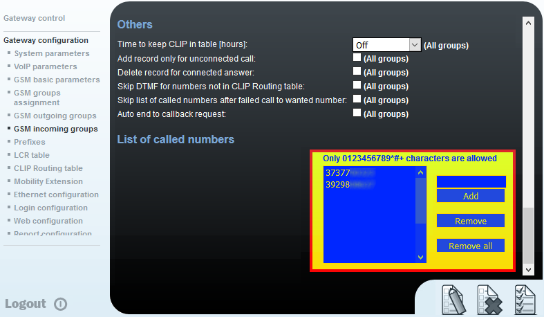
In the List of called numbers table, enter the company numbers with which the gateway will contact the PBX, one for each SIM and one for each row. They can be convenient numbers, but for greater clarity it is advisable to use the true number of each SIM.


